
The Essential Guide to Cutting Discs: Installation, Hole Rings & Fitment Demystified
For professionals and DIY enthusiasts alike, the angle grinder is an indispensable tool. Yet, its effectiveness and, critically, your safety, hinge entirely on the correct mounting and understanding of the cutting or grinding disc. Questions about proper installation, inconsistencies in the center hole ring, and the importance of hole size are fundamental. Let’s delve into the technical details to ensure you work efficiently and safely.
Mastering the Installation–How to Correctly Mount a Cutting Disc on Your Angle Grinder

Installing a disc seems simple, but errors here are a primary cause of catastrophic failures. Follow these steps meticulously.
- Power Down & Unplug:This is non-negotiable. Never attempt to change a disc while the grinder is connected to a power source. Accidental activation can cause severe injury. Confirm the tool is completely off and disconnected.
- Depress the Spindle Lock: Locate the spindle lock button, usually near the spindle nut. Press and hold it firmly. This prevents the spindle from rotating while you loosen the retaining nut. Do not rely on gripping the disc itself to hold the spindle.
- Remove the Outer Flange (Retaining Nut):Using the correct size spanner (usually supplied with the grinder), turn the nut counter-clockwise (standard thread). Apply firm pressure while holding the spindle lock. Some nuts have two holes for a pin spanner, others have flats for an open-end wrench. Use the correct tool to avoid damage.
- Remove the Old Disc:Carefully take off the old disc. Inspect the inner flange (the washer seated directly against the grinder body) for damage, wear, or debris. Clean it if necessary.
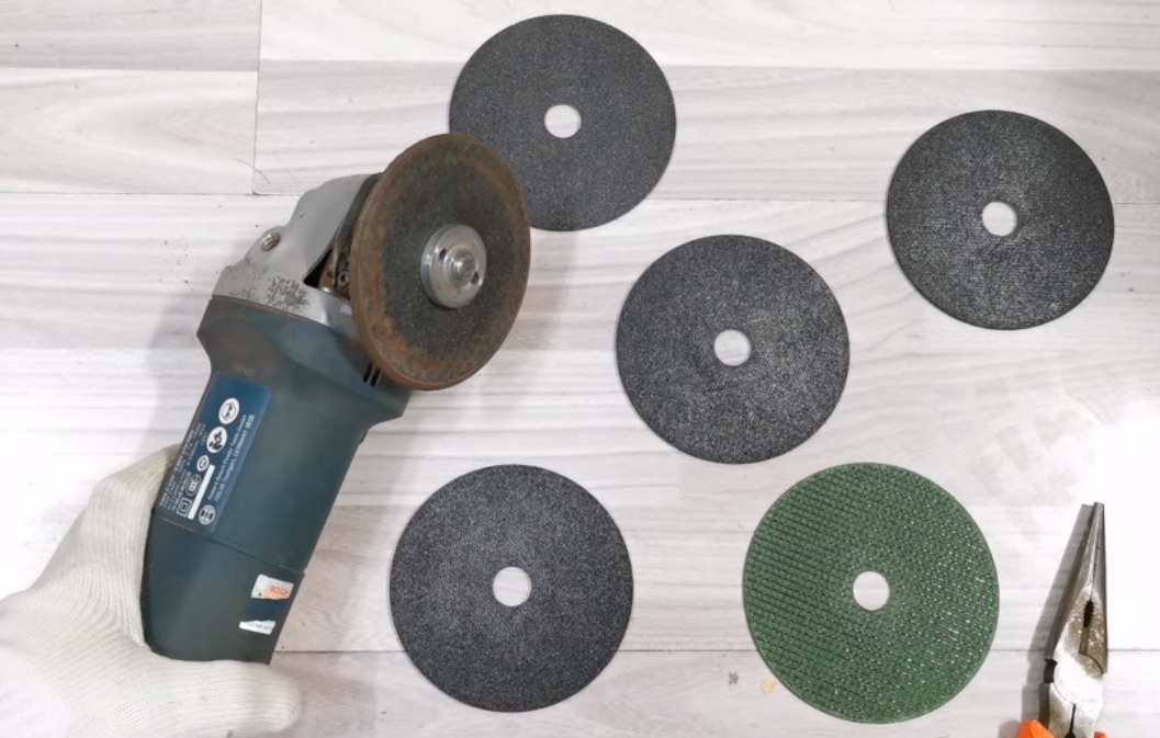
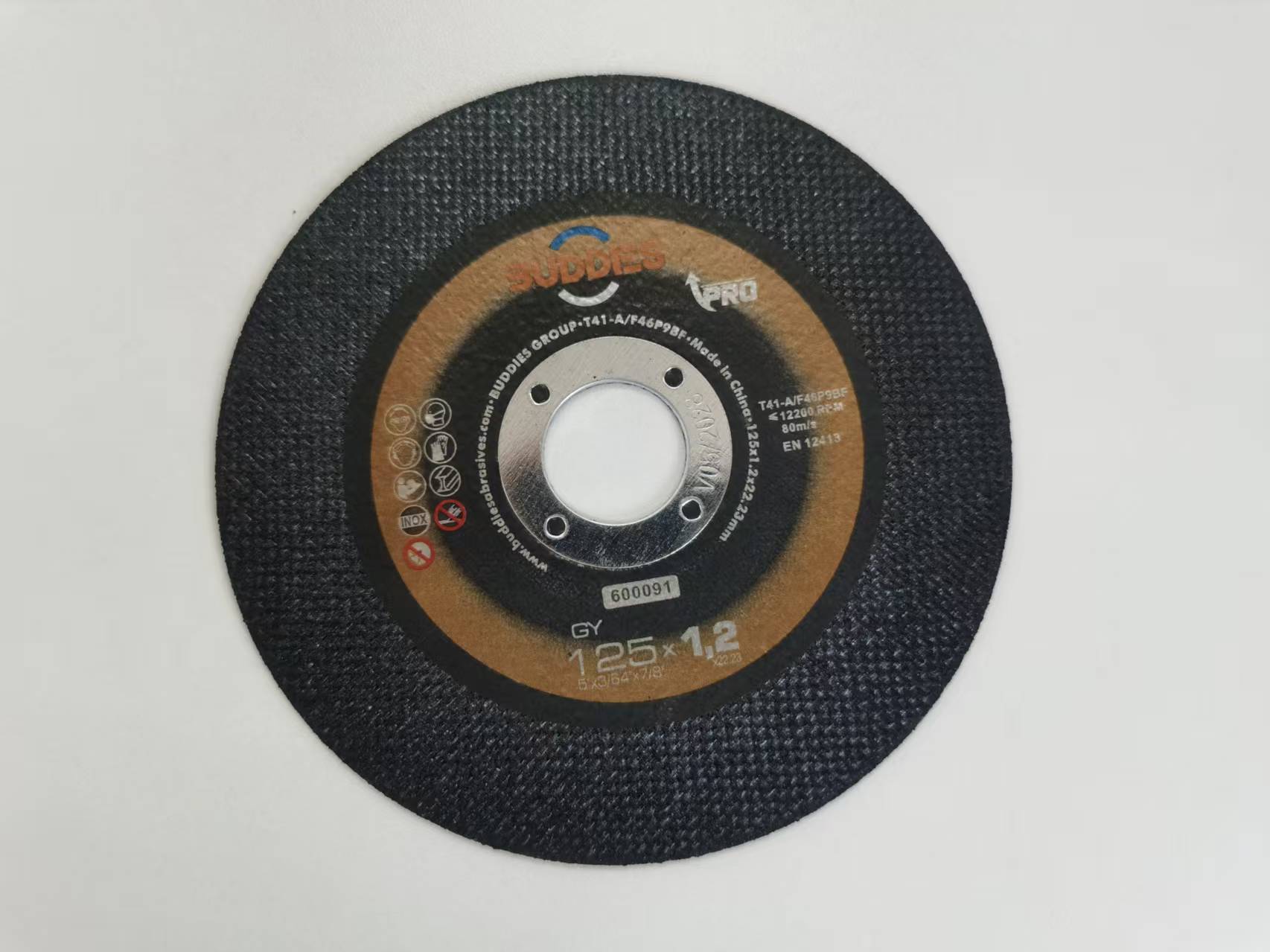
- Prepare the New Disc: Inspect the new disc thoroughly before mounting. Look for cracks, chips, or any signs of damage. Do not use a damaged disc. Check the Maximum Operating Speed (RPM) rating on the disc label – it MUST equal or exceed the RPM rating of your angle grinder. Using an under-rated disc is extremely dangerous. Verify the disc type (cutting vs. grinding) and that the bore size matches your grinder spindle (common sizes are 22.23mm / 7/8″ for most angle grinders).
- Mount the New Disc:Place the disc onto the spindle shaft, ensuring it sits flat against the inner flange. The inner flange is crucial as it provides a solid, flat backing surface for the disc, distributing clamping force evenly and preventing distortion. Crucially, ensure the disc’s labeled side faces outward. Most discs have specifications, warnings, or brand markings on one side – this side must face away from the tool body. Mounting it backward can compromise performance and safety.
- Replace the Outer Flange: Slide the outer flange (retaining nut) over the spindle shaft and hand-tighten it clockwise. Ensure it sits flat against the disc. The outer flange often has a raised center section that fits into the disc’s bore.
- Secure the Outer Flange:While firmly depressing the spindle lock, tighten the outer flange clockwise using the spanner. Apply firm, even pressure. Do not overtighten. Excessive force can crack the disc, distort it, or damage the flanges. Tighten sufficiently to prevent slippage under load – typically, a good hand-tightening plus a moderate quarter to half turn with the wrench is adequate. Refer to your grinder manual if unsure. Avoid using impact wrenches.
- Final Checks:Visually confirm the disc is centered. Ensure there’s no wobble apparent just by looking at it. Keep your face and body away from the disc plane. Briefly run the grinder (unplugged first if using a guard) at no load for a few seconds in a safe direction. Listen for unusual sounds and observe for excessive vibration. If anything seems amiss, stop immediately, power down, unplug, and recheck the installation.
Safety is Paramount:
- Always use the correct guard designed for the disc size and operation (cutting/grinding). Position it between you and the debris/spark stream.
- Wear ANSI Z87.1+ impact-rated safety glasses or a face shield, hearing protection, gloves, and sturdy work clothes.
- Ensure the workpiece is securely clamped.
- Never force the tool; let the disc cut or grind at its own pace.
- Never use a cutting disc for grinding or vice-versa. Their construction differs significantly.
Understanding Center Hole Rings–Why Might They Be Inconsistent?
The center hole ring, often a reinforced fiberglass or resin area surrounding the bore, is vital for structural integrity and force distribution. Finding slight variations between the “top” and “bottom” sides of this ring is common and usually not a defect. Here’s why.

- Manufacturing Process (Molding & Pressing): Cutting discs are typically made by pressing layers of abrasive grains, fillers, and bonding agents (like resin) between reinforcing fiberglass mesh in a mold under high heat and pressure. The orientation of the mesh layers and the flow of the resin during pressing can naturally lead to subtle differences in how the material consolidates around the hole on each face. This is inherent to the process and doesn’t inherently weaken the disc if within tolerance.
- Reinforcement Mesh Alignment: The fiberglass mesh layers are the backbone. During the layering process before pressing, slight shifts in alignment can occur. This means the mesh might sit fractionally closer to one surface than the other near the hole, influencing the appearance and texture of the ring on each side.
- Surface Finishing: After pressing and curing, discs often undergo finishing processes like balancing or labeling. Handling during these stages or slight variations in how the disc sits during labeling might cause minor cosmetic abrasions or differences in resin flow appearance on one ring surface versus the other. This is typically superficial.
- Material Flow & Cure: The viscous resin mixture flows under pressure during molding. Variations in flow dynamics around the central mandrel (which forms the hole) can result in slightly different textures or resin richness on opposing faces of the hole ring. Similarly, minor temperature gradients during the curing cycle might affect surface characteristics locally.
- Permitted Tolerances: International standards (like ISO 603 for bonded abrasives) recognize that minor variations are inherent. Specifications often allow for small dimensional tolerances and cosmetic differences in the hole ring area as long as the core functionality – providing a strong, stable mounting surface – is maintained. The ring’s primary job is to prevent the clamping force of the flanges from crushing the abrasive material and to distribute rotational stresses.

When is Inconsistency a Problem?
- Physical Damage: Cracks, chips, or significant crumbling in the hole ring area.
- Severe Deformation: Noticeable warping or bending of the ring itself.
- Excessive Asymmetry Leading to Wobble: If the inconsistency is so pronounced that the disc cannot sit flat against the inner flange, causing visible wobble even when correctly mounted, it’s unsafe.
- Loose Material: If fiberglass strands are fraying excessively or resin is flaking off significantly around the hole.
Minor visual or textural differences between the two sides of the hole ring, without physical damage or functional impairment, are generally acceptable and reflect the manufacturing realities. The disc’s performance and safety rely more on the integrity of the bonding and reinforcement throughout the entire structure.
Does Center Hole Size Really Matter? Absolutely.
The center hole (bore) size is not a suggestion; it’s a critical safety specification. Using a disc with an incorrect bore size is dangerous and can lead to disc failure.
1. Fundamental Fit: The disc’s bore must match the diameter of your angle grinder’s spindle shaft. Common standard sizes are:
- 22.23 mm (7/8 inch): The overwhelming standard for most professional and DIY angle grinders (e.g., Bosch, Makita, DeWalt, Milwaukee, Metabo).
- M14: Less common, found on some older or specific regional models.
- 16 mm / 20 mm / 25.4 mm (1 inch): Used on some larger industrial grinders or specialized tools.
- Arbor Bushes: Some discs come with removable plastic or metal bushes (e.g., a 25.4mm disc with a 22.23mm bush). Ensure the bush is securely fitted and the effective bore size matches your spindle.
2. Consequences of an Oversized Hole:
- Eccentric Rotation & Severe Vibration: The disc will not be centered on the spindle. Even a fraction of a millimeter mismatch causes significant wobble as the disc spins at high RPM. This is immediately noticeable and uncomfortable.
- Increased Stress & Risk of Breakage: Eccentric rotation creates immense unbalanced centrifugal forces and bending stresses within the disc. These forces can easily exceed the disc’s structural limits, leading to catastrophic disintegration.
- Poor Cutting/Grinding Performance: Vibration reduces control, accuracy, and cutting efficiency, often leading to gouging or uneven results.
- Tool Damage: Excessive vibration damages the grinder’s bearings and gears over time.
- Slippage: The disc can slip on the spindle under load, especially if the clamping force isn’t perfectly centered, further increasing the risk of breakage or loss of control.
3. Consequences of an Undersized Hole:
- Inability to Mount: The disc simply won’t fit onto the spindle shaft.
- Forcing the Disc: Attempting to force an undersized disc onto the spindle can crack or chip the center hole ring immediately, compromising its integrity before you even start the tool. Never enlarge the hole yourself by drilling, grinding, or filing. This destroys the reinforced ring, creates stress points, and guarantees failure.
Tolerance is Minimal: While manufacturing tolerances exist (typically a bore size tolerance of +0.1mm / -0.0mm or similar, as per standards like ISO 603), the disc must fit snugly on the spindle without play. There is no safe “close enough.” The fit must be precise.
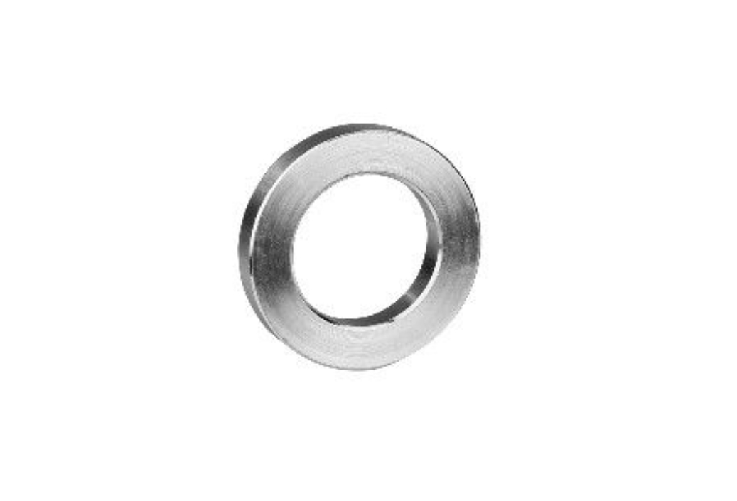
Arbor Adapters are NOT the Solution: Never use makeshift washers, shims, or reducers to adapt a disc to a different spindle size. These compromise the critical flat contact between the disc and the inner/outer flanges, creating uneven pressure points and high risk of failure. Only use purpose-designed, factory-supplied bushes integrated into the disc itself.
Troubleshooting Common Mounting & Operation Issues

| Symptom | Potential Cause(s) | Solution |
| Excessive Vibration | 1. Disc incorrectly mounted (not flat, backward). 2. Incorrect bore size. 3. Damaged disc (cracked, chipped). 4. Uneven disc wear. 5. Damaged/worn inner or outer flange. 6. Grinder spindle bent (rare). |
1. Stop! Power down, unplug, re-mount carefully. 2. Verify bore size match. 3. Discard damaged disc. 4. Replace disc. 5. Replace damaged flanges. 6. Service grinder. |
| Disc Wobble (Visible) | 1. Incorrect bore size (oversized). 2. Flanges not seated flat/damaged. 3. Debris between disc and flange. 4. Severe disc warp/damage. |
1. Use correct bore size disc. 2. Clean flanges, ensure flat, replace if damaged. 3. Clean mounting surfaces. 4. Discard disc. |
| Disc Slipping | 1. Outer flange not tightened sufficiently. 2. Worn/damaged flanges (smooth surfaces). 3. Contamination (oil, grit) on flanges/disc. 4. Using disc without center hole ring (e.g., some diamond blades). |
1. Tighten correctly (firm, not excessive). 2. Replace flanges. 3. Clean all contact surfaces. 4. Use only discs designed for flangeless mounting if your grinder supports it (rare for abrasives). |
| Nose Breakage (Disc Shatters at Center) | 1. Overtightening the outer flange. 2. Using an oversized bore disc. 3. Damaged center hole ring. 4. Severe impact on disc center. 5. Poor quality disc. |
1. Tighten correctly. 2. Use correct bore size. 3. Inspect hole ring before use, discard damaged discs. 4. Handle discs carefully. 5. Source discs from reputable manufacturers. |
| Disc Wearing Unevenly | 1. Applying uneven pressure during use. 2. Grinder not held perpendicular to workpiece. 3. Disc quality/defect. 4. Incorrect disc type for material. |
1. Practice technique, apply even pressure. 2. Maintain correct angle. 3. Try disc from different batch/manufacturer. 4. Select appropriate disc. |
Advanced Considerations: Torque and Storage
- Torque: While precise torque specs are rarely provided for angle grinder nuts, the principle of “firm but not excessive” is key. Over-tightening is a common cause of center ring cracks. If your grinder manual specifies a torque, use a torque wrench. Otherwise, hand-tight plus a moderate fraction of a turn with the wrench is sufficient.
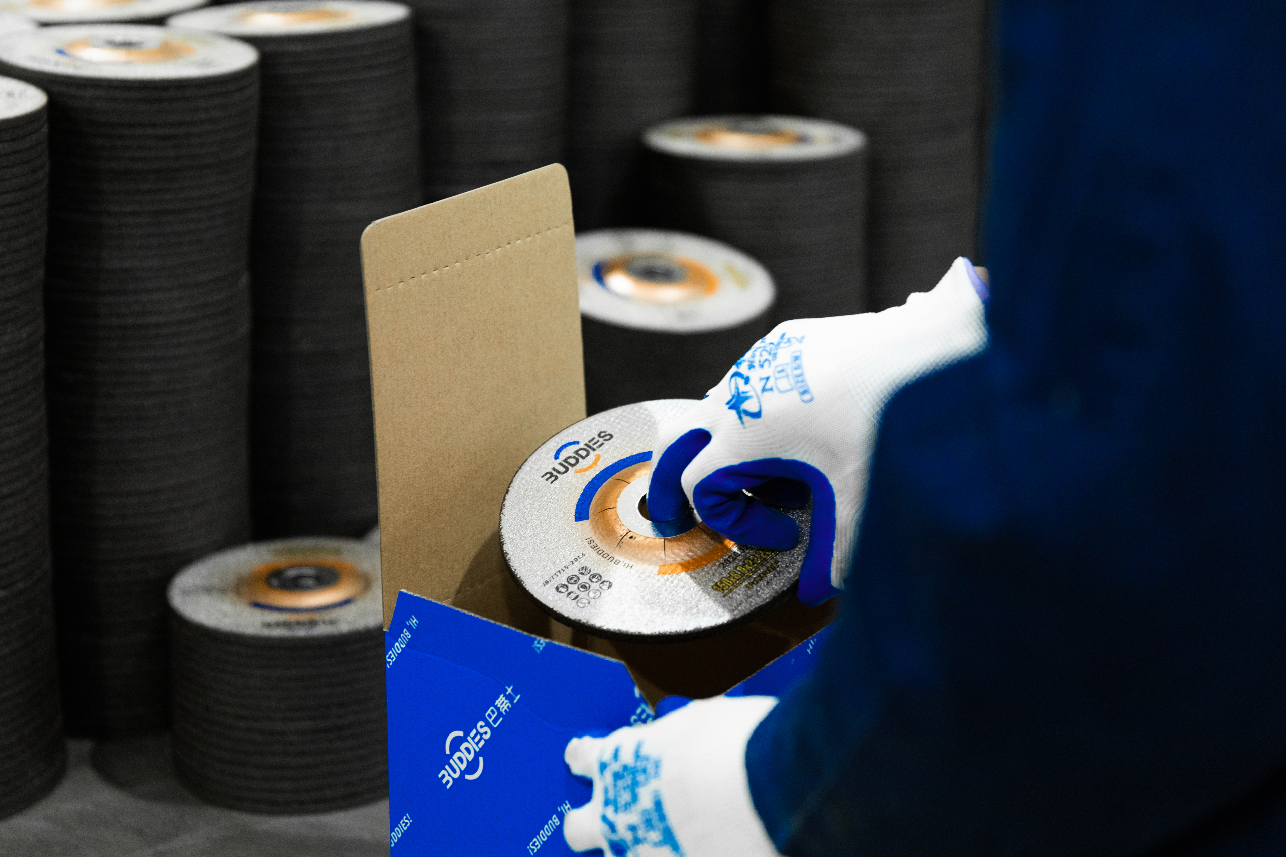
- Storage: Store discs flat in a dry, temperature-stable environment away from direct sunlight and moisture. Avoid stacking excessive weight on them. Damp conditions can degrade resin bonds, and physical stress can warp discs or damage hole rings.
Conclusion: Knowledge is Safety
Correctly mounting your cutting or grinding disc, understanding the reasons behind minor center hole ring variations, and strictly adhering to the specified bore size are not mere technicalities – they are the bedrock of safe and effective angle grinder operation. By following the precise installation steps, recognizing acceptable manufacturing tolerances in the hole ring, and never compromising on the correct bore size, you significantly mitigate the risk of dangerous disc failures. Always prioritize quality discs from reputable manufacturers, inspect them thoroughly before each use, and never hesitate to discard a disc that shows any signs of damage or doesn’t fit perfectly. Your safety and the quality of your work depend on these fundamental practices. Consult your angle grinder manual and disc manufacturer specifications for the most precise information regarding your specific equipment. Work smart, work safe.
This post is also available in:


Leave a Reply
Want to join the discussion?Feel free to contribute!